Do-it-yourself passive emitter meter circuit. DIY electromagnetic radiation detector. Schemes of homemade security and information protection devices
I would like to present a diagram of a device that is sensitive to high-frequency electromagnetic radiation. In particular, it can be used to indicate incoming and outgoing mobile phone calls. For example, if the phone is on silent mode, then this device will allow you to notice faster incoming call or SMS.
All this fits on a 7 cm long mounting plate.
The majority of the board is occupied by the display circuit.
There is also an antenna here.
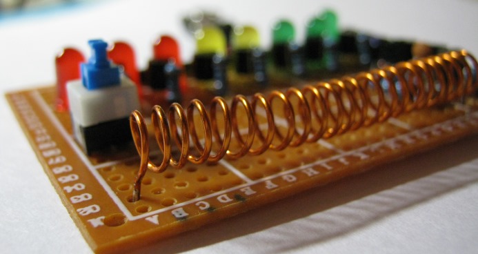
The antenna can be a piece of any wire at least 15 cm long. I made it in the form of a spiral, similar to a coil. Its free end is simply soldered to the board so that it does not dangle. Many different antenna shapes have been tried, but I have come to the conclusion that it is not the shape that is important, but rather the length of the antenna, which you can experiment with.
Let's look at the diagram.
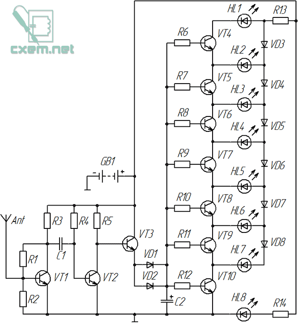
An amplifier based on transistors is assembled here.
KT3102EM was used as transistor VT1. I decided to choose it because it has very good sensitivity.
All other transistors (VT2-VT10) are 2N3904.
Let's consider the indication circuit: transistors VT4-VT10 are the key elements here, each of which turns on the corresponding LED when a signal arrives. Any transistors of this scale can be used, even KT315, but when soldering it is more convenient to use transistors in the TO-92 package due to the convenient location of the terminals.
Threshold diodes (VD3-VD8) are used here, and therefore only one LED lights up at any time, indicating the signal level. True, this does not happen in relation to the radiation of a mobile phone, since the signal constantly pulsates at a high frequency, causing almost all LEDs to glow.
The number of “LED-transistor” cells should not be more than eight. The values of the base resistors are the same here and amount to 1 kOhm. The rating will depend on the gain of the transistors; when using KT315, 1 kOhm resistors should also be used.
It is advisable to use Schottky diodes as diodes VD1, VD2, since they have a lower voltage drop, but everything works even when using the common 1N4001. One of them (VD1 or VD2) can be excluded if the indication is too high.
All other diodes (VD3 - VD8) are the same 1N4001, but you can try using any you have on hand.
Capacitor C2 is electrolytic, its optimal capacity is from 10 to 22 μF, it delays the extinguishing of the LEDs for a fraction of a second.
The value of resistors R13 AND R14 depends on the current consumed by the LEDs, and will range from 300 to 680 Ohms, but the value of resistor R13 can be changed depending on the supply voltage or if the LED scale is insufficiently bright. Instead, you can solder a trimmer resistor and achieve the desired brightness.

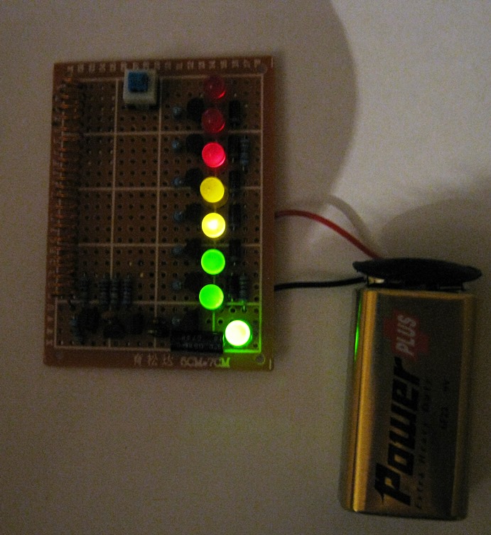
There is a switch on the board that turns on a certain “turbo mode” and passes current bypassing resistor R13, as a result of which the brightness of the scale increases. I use it when powered by a Krona battery, when it runs low and the LED scale dims. The switch is not indicated on the diagram, because it is not required.
Once power is applied, the HL8's LED will light up immediately and simply indicate that the device is turned on.
The circuit is powered with voltage from 5 to 9 Volts.
Next, you can make a case for it, for example, from transparent plastic, and foil PCB can be used as a base. By connecting an antenna to the metallization of the board, it may be possible to increase the sensitivity of this indicator of high-frequency radiation.
By the way, it also reacts to microwave radiation.
List of radioelements
| Designation | Type | Denomination | Quantity | Note | Shop | My notepad |
|---|---|---|---|---|---|---|
| VT1 | Bipolar transistor | KT3102EM | 1 | To notepad | ||
| VT2-VT10 | Bipolar transistor | 2N3904 | 9 | To notepad | ||
| VD1 | Schottky diode | 1N5818 | 1 | Any Schottky diode | To notepad | |
| VD2-VD8 | Rectifier diode | 1N4001 | 7 | To notepad | ||
| C1 | Ceramic capacitor | 1 - 10 nF | 1 | To notepad | ||
| C2 | Electrolytic capacitor | 10 - 22 µF | 1 | To notepad | ||
| R1, R4 | Resistor | 1 MOhm | 2 | To notepad | ||
| R2 | Resistor | 470 kOhm | 1 | To notepad | ||
| R3, R5 | Resistor | 10 kOhm | 2 |
In addition to the multimeter, of course, you need to have a special indicator of the emitted electromagnetic field. And it is desirable to assemble a broadband circuit capable of responding to frequencies from FM to GSM without modification. This is exactly the kind of detector we will make. The circuit of this field indicator is an amplifier DC on an operational amplifier with a UHF stage and an RF detector. A filter is installed at the UHF input high frequencies L1, C2, L2, C3, which cuts off signals with a frequency below 10 MHz, otherwise the device begins to respond to electrical wiring background and other interference. The RF amplifier is made according to a common emitter circuit; the mode is set by resistor R1 so that the collector VT1 has a voltage equal to half the supply voltage.
Through capacitor C4, the signal is supplied to the diode detector VD1, here it is necessary to use microwave germanium diode GD402, GD507, diode D9 cannot be used, maximum frequency which is 40 MHz. The rectified signal is supplied to the input of the op-amp through filter L3, L4, C6, C7, which prevent the RF component from entering the input of the op-amp. The operational amplifier runs on unipolar power supply, therefore, for its normal operation, using a divider by R4; R5 created an artificial “midpoint”. The gain of the microcircuit is determined by the ratio R6/R8 at small input signals. When the voltage at pin 6 of the microcircuit increases to 0.6 volts, the diode VD2 opens and into the circuit feedback resistor R7 is connected to the amplifier, which reduces the gain and makes the device scale linear.
As an op-amp, you can use 140UD12 or 140UD6. If you use UD6, resistor R9 must be removed from the circuit. Resistor R10 sets the device scale to 0. VT1 is a microwave transistor, for example KT399. Coil L1 - 8 turns, 0.5 wires on a 5 mm mandrel, L2 - 6 turns of the same wire. Chokes L3, L4 50 - 100 μH each.

The following circuit is a modified design; the use of an additional op-amp made it possible to eliminate the resistor voltage divider and improve the characteristics of the device. The circuit is very simple and should not cause difficulties in manufacturing and configuration.

This design is capable of detecting:
- Radio microphone V Pit=3 V. F=93 MHz - 4 meters.
- Radio microphone, single transistor, Vpit=3 V. F=420 MHz - 3 meters.
- Radio microphone Vpit=3 V. F=860 MHz - 80 cm.
- Chinese TV camera Vpit=9V. F=1200 MHz. - 4 meters.
- Mobile phone, during transmission - up to 7 meters.
Are you fed up with your neighbors' loud music or just want to make some interesting electrical equipment yourself? Then you can try to assemble a simple and compact electromagnetic pulse generator that is capable of disabling electronic devices nearby.
An EMR generator is a device capable of generating a short-term electromagnetic disturbance that radiates outward from its epicenter, thereby disrupting the operation of electronic devices. Some EMR bursts occur naturally, for example in the form of electrostatic discharge. There are also artificial EMP bursts, such as a nuclear electromagnetic pulse.
IN this material It will be shown how to assemble a rudimentary EMP generator using commonly available items: a soldering iron, solder, a disposable camera, a push-button switch, insulated thick copper cable, enamel-coated wire, and a high-current latched switch. The presented generator will not be very powerful in terms of power, so it may not be able to disable serious equipment, but it can affect simple electrical appliances, so this project should be considered as a training project for beginners in electrical engineering.
So, first, you need to take a disposable camera, for example, Kodak. Next you need to open it. Open the case and locate the large electrolytic capacitor. Do this with rubber dielectric gloves to avoid getting an electric shock when the capacitor is discharged. When fully charged, it can show up to 330 V. Check the voltage on it with a voltmeter. If there is still a charge, remove it by shorting the capacitor terminals with a screwdriver. Be careful, when shorted, a flash will appear with a characteristic pop. After discharging the capacitor, remove the circuit board it is mounted on and locate the small on/off button. Unsolder it, and in its place solder your switch button.

Solder two insulated copper cables to the two terminals of the capacitor. Connect one end of this cable to a high current switch. Leave the other end free for now.

Now you need to wind the load coil. Wrap the enamel-coated wire 7 to 15 times around a 5cm diameter round object. Once the coil is formed, wrap it with duct tape to make it safer to use, but leave two wires protruding to connect to the terminals. Use sandpaper or a sharp blade to remove the enamel coating from the ends of the wire. Connect one end to the capacitor terminal and the other to a high-current switch.

Now we can say that the simplest electromagnetic pulse generator is ready. To charge it, simply connect the battery to the appropriate pins on the capacitor circuit board. Bring some portable electronic device that you don't mind to the coil and press the switch.

Remember not to hold down the charge button while generating EMP, otherwise you may damage the circuit.
Ultrahigh frequency (UHF) radiation or so-called microwave radiation has an adverse effect on the human body. To protect yourself and your loved ones from the consequences of this type of radiation, detectors of varying complexity are used to detect the leakage of radiation from microwave ovens, cell phones and other devices. How to identify a dangerous device — We’ll talk about this in this article.
Photo. 1. Appearance of a Panasonic household microwave oven
Not everything that is written in the operating instructions for household appliances (especially translated manuals) is true. Most often, this is a so-called half-truth: on one side everything seems to be true, but it often turns out that something is left unsaid. The same applies to phenomena and processes that can be dangerous to the life and health of a person or his things.
Not so long ago, the time has passed (or maybe not yet) when portable household dosimeters were extremely popular among the population. No, of course, not every family had an apartment, country house a nuclear reactor, but the products and things that were bought from hand and in markets clearly required control. No, no, and the dosimeter went off scale... For the same reason, today people buy devices to measure the level of pesticides in various fruits of nature.
One of the sources of adverse effects on the human body is ultrahigh frequency (UHF) radiation or so-called microwave radiation. A striking example electronic device with a microwave radiation generator (magnetron) is a microwave oven (see Fig. 1).
In addition to potentially dangerous microwave radiation for humans and animals, a microwave oven (hereinafter referred to as the oven) creates strong electromagnetic radiation, which has a negative effect on some objects and things - for example, wristwatches with an electromagnetic system (and others).

Photo. 2. Panasonic microwave oven with the housing cover removed
Generally, a new oven will operate reliably and will not emit harmful radiation outside its housing, but it is still best to avoid placing watches, cell phones, or other items on it.
Stove that was being repaired outside service center, in which the main element of the generator - the magnetron - was replaced, with a damaged housing or having damage to the working chamber, waveguide and other deficiencies, is potentially hazardous to health.
To identify such harmful ovens and other devices (for example, a broken mobile phone), microwave radiation indicators are used. The simplest diagram of such an indicator is shown in photo 3.

Photo 3. Simple scheme microwave radiation indicator, which you can assemble yourself
Note to photo 3. A loop is a piece of copper wire with a diameter of 1...1.5 mm. Electric spot welding wire is quite suitable for this purpose. Microwave diode - diode type 2A202A, DK-V8 or similar. The tester is a milliammeter with a full needle deflection current of 100 µA. In our case, it is better to use a pointer device, for example, Ts4342, Ts4317 or similar. Non-polar capacitor - any, for example, MBM type.
The junction of the magnetron with the power source contains transition capacitors, which (together with the chokes) form a filter to protect against the penetration of microwave radiation from the magnetron and the waveguide to the outside.
The principle of checking a microwave oven is simple - a “loop” with a microammeter is slowly passed next to the body of the microwave oven (at a distance of 1-6 cm from it). Slow speed“scanning” is needed in order to record microwave radiation in the most dangerous zone of the oven.
The microwave radiation generator is turned on in the oven during cooking not constantly, but periodically. This is also noticeable visually: the backlight inside the oven’s working chamber dims a little, and the oven makes a little more noise when the generator is turned on.
What don't we know about the magnetron?
The most important component of a microwave oven is a magnetron, which is an electric vacuum diode designed to generate microwave oscillations. When the magnetron operates, power is released, which turns into heat, so a thermal electromagnetic field is created inside the working chamber. The power generated by the magnetron is supplied through a waveguide - a device that transmits energy to the working area of the furnace, which is a rectangular chamber (working chamber).

Photo 4. Close-up of the magnetron
Next to the waveguide output there is a rotating table on which the product to be processed is placed. All this is located inside the furnace body.
It is important that the radiation (hazardous to life if directly exposed to a person) does not extend beyond the furnace body. The furnace body is a closed metal structure, which at the same time serves as a screen for microwave radiation.
For household heat treatment in the microwave range, they are used electromagnetic vibrations at frequencies of 2375, 2450 MHz - in very old models, and up to 10-12 GHz in modern furnaces. In table 1 provides information on the depth of penetration of an electromagnetic wave (with energy losses) into some of the dielectrics.
Table 1. Penetration depth of an electromagnetic wave in a dielectric with losses at a temperature of 20-25 ºС
Modern magnetrons (magnetrons with a non-heated field cathode type MI and similar) provide “instant” (from the first pulse) readiness to operate at full power without wasting energy on heating the cathode, which significantly increases the reliability of the magnetron.
The use of a non-heated magnetron made it possible to simplify electrical diagram ovens, excluding dozens of radio components. In this regard, there is no need for a transformer, a control device and a voltage regulator in the magnetron filament circuit (since there is no filament itself), master and blocking generators, it was possible to reduce the weight and dimensions of the furnace, reduce the cost of the product, while simultaneously increasing its operational reliability.
Possible malfunctions of magnetrons:
The anode of the magnetron is made in the form of a copper cylinder. Operating voltage The magnetron anode (depending on the type) ranges from 3800 to 4000 V. Power from 500 to 1200 W. The magnetron is mounted directly on the waveguide (Fig. 3). In furnaces where the manufacturer places a magnetron with a short waveguide, a defect such as breakdown of the mica gasket can be observed. This happens as a result of contamination of the gasket;
when the gasket breaks down, the magnetron cap melts (this happens with magnetrons of the type 2M-218N(R), OM7S(20), 2M213-09F, 2M-219N(V), 2M226-09F and structurally similar). It (the cap) can be replaced with a similar cap from another magnetron;
Like any lamp, it can lose its emission, resulting in a significant reduction in energy output and an increase in cooking time. Usually average term magnetron service life (for example, 2M213-xx) has a limit of 15,000 hours. Its efficiency is 75-80%, which is an effective indicator for magnetrons of microwave oscillation generators;
breakdown of transition capacitors can be detected using a tester in resistance measurement mode. The breakdown occurs on the magnetron housing. The malfunction is eliminated by replacing the entire assembly.
Separately, the magnetron can be checked only by generating all the voltages necessary for its operation.

Photo 5. Microwave oven power supply
In a microwave oven, the second most important element after the magnetron is the power supply (Photo 5). The entire safe operation of the furnace depends on its reliability.
A wonderful tool for repairing and diagnosing microwave ovens, in particular when diagnosing magnetrons, are current clamps, for example, ECT-650 “Escort”.
They allow you to measure the current consumed by the furnace, the current of the high-voltage winding of the transformer. The rated current consumed by the furnace is 4.5 - 6 A, the current of the high-voltage winding of the transformer is 0.3 - 0.5 A.
Large deviations from the specified values (especially in the direction of increasing individual parameters) indicate a local malfunction of the magnetron.
At the same time, an underestimation of all parameters can be explained by poor contacts, starting from the power socket and ending with switching elements (relays, electrical microswitches, contacts).
In order to make sure that the magnetron is working properly and that there is a sufficient level of microwave radiation inside the furnace body, it is checked with a detector.
Microwave Radiation Detectors
Photo 6 shows an industrial microwave radiation detector, which can be purchased at electrical goods stores.

Rice. 6. Microwave radiation detector
This device detects only microwave pulses, which can be checked by bringing the device directly to its walls while the oven is operating. It will also be useful for searching for “bugs” operating at ultra-high frequencies, searching for cell phones and checking their operation. Such an industrial tester costs less than 500 rubles.
The device is powered by a 6F22 Krona battery with a voltage of 9 V. The current consumption of the device in standby mode is a few µA, so the battery lasts a long time. An indicator LED is located at the top of the case.
It will light up when microwave radiation is present in the detector area (shown on the body by an arrow). The device does not measure radiation power, but records its presence.
Using such a detector, you can check not only the working chambers of microwave ovens and the presence of harmful radiation outside their housing, but also the presence of radiation from cell phones. It's easy to do.
It is necessary to bring the detector to a possible source of radiation, for example, to the body of a mobile phone at a distance of 2-10 cm. When the cell phone is active: with incoming and outgoing call, unauthorized “communication” of a cell phone with base station, when registering a cell phone on the network (for example, when turning on the cell phone) and in other cases, the detector indicator will show the presence of microwave radiation.
It wouldn’t hurt to use this visual lesson in physics lessons in schools, so that people understand how harmful or beneficial it is to constantly wear cell phone close to your own body (on your chest, on your belt, in your pocket, especially your chest).
The results of harmful microwave radiation (especially with constant exposure) are probably better commented on by scientists and medical professionals. On my own behalf, I will only add that microwave radiation is like an atom, which can be peaceful or not. This must be clearly understood when using a seemingly harmless mobile phone or microwave oven.
Another industrial device intended for motorists, called a “spark indicator,” can also be used as a microwave radiation detector. Such devices are commercially available, one of which is shown in Fig. 7.

Rice. 7. Photo ( appearance) microwave radiation detector — spark indicator
The device is designed to test high-voltage ignition circuits of cars. A sensor is installed inside the case (the same loop as in the diagram in Fig. 5, only in miniature), which, as practice has shown, responds not only to high impulse voltage in the ignition of a car, but also in the microwave radiation of a microwave oven and a cell phone.
A red LED located near the “high voltage” arrow also serves as an indicator of microwave radiation.
On remote wires, the indicator is powered from any power source with constant voltage 8-15 V, including from a Krona battery or car battery.
The peculiarity of the device is that it has sensitivity adjustment (the adjustment knob is located on the top of the body). Such a device costs around 300 rubles. Having it, you no longer have to worry about other microwave radiation detectors.
Safe work measures during repair and maintenance of microwave ovens
Failure to follow these rules may result in failure electric shock, injuries and failure of quite expensive components of the microwave installation.The most dangerous (of all available in domestic conditions) for humans is AC frequency 50 Hz, as well as microwave radiation.
A microwave oven connected to a 220 V network (under voltage) can be repaired and checked only in cases where it is impossible to perform work in a device disconnected from the network (setup, adjustment, measuring modes, searching for bad contacts in the form of “cold soldering” and similar cases).
Care must be taken to avoid exposure to dangerous voltage.Avoid burns from heating elements.
In all cases of working with the oven turned on, it is necessary to use tools with insulated handles. You should work with one hand, wearing long sleeves or oversleeves.
At this time, you must not touch the stove body or other grounded objects (central heating pipes, water supply) with your other hand. Wires measuring instruments must end with probes and have good insulation.
This general rules electrical safety.
Attention, dangerous:
soldering of furnace elements under voltage;
repair the stove included in electrical network, in a damp room, or with a cement or other conductive floor;
is located near the installation by persons not repairing it;
Like any source of microwave radiation, direct exposure to magnetron radiation can cause eye damage or skin burns. The human eye cannot see microwave radiation;
When replacing the magnetron, be especially careful. Do not leave installation debris in the waveguide;
Before replacing, always dilute the capacitor in the magnetron power supply circuit with a piece of insulated wire (the shunt resistor sometimes fails).
In addition, when operating the stove it is not allowed:
turn on the oven with the door or screen open (it will not turn on itself, since there is protection for that, but this point is relevant for those who neglect this protection by turning it off);
you can’t make holes in the body (housewives who dream of hanging the stove on the wall like a bread box should stop thinking like that).
Schemes of homemade security and information security devices
As we know, all information theft devices, radio bugs and simply telephones operate by transmitting at radio frequencies and, therefore, create a magnetic field around themselves.
Exactly according to availability electromagnetic radiation and such a device can be detected and further consequences from its use can be prevented.
A diagram of a device that allows you to determine the presence of an electromagnetic field is shown in the figure.
The device is convenient to use for monitoring the operation and setting up low-power transmitting devices operating in wide range frequency Operating frequency is 20-1300 MHz, sensitivity is 1 mV, localization limits are within 0.05-7 m. The supply voltage is 4.5-9 V, and the current consumption does not exceed 8 mA. The device has a telescopic antenna.
Electromagnetic field indicator circuit
This device is intended for local search of radio bookmarks. His distinctive features are:
- ease of repetition;
- reliability;
- small dimensions.
Note. And this device has a drawback - it reacts a little to extraneous radio emissions from television and radio broadcasting stations and radiotelephones. But this drawback is more than compensated for by the simplicity and low cost of the indicator.
The input signal induced by the telescopic antenna is fed to the RF input amplifier, built on the transistor VT1, and then, through the filter Cl, L1, SZ to the detector-comparator DA1.
The threshold for turning on the comparator is set by resistor R5. The comparator signal from output 6 through the inverter DD1.3 and the key VT2 controls the square pulse generator on elements DD1.4, DD1.5 with a frequency of 1 Hz, which, in turn, turns on the audio frequency generator on DD1.1, DD1.2.
LED VD1 - two-color:
- VD1.1 signals power on with green light;
- VD2.2 signals the detection of a radio source with red light.
Setting up the device consists of selecting op-amp DA1 with the highest possible gain.
Note. The distance at which the indicator should stably respond, having an antenna 30 cm long, to a radio transmitter with a power of 1 mW, must be at least 50 cm.
Transistor KT3101 can be replaced with KT371, KT368 with a gain of at least 150. Operational amplifier - K140UD608, K140UD708.
The ALC331 LED can be replaced with conventional ones, such as AL307, by turning them on instead of VD1.1 and VD1.2. The inductor has 19 turns, wound in a row on any MLT 0.125 resistor, with PEL-0.1 wire.