Start in science. Tesla coil and demonstration of the incredible properties of the electromagnetic field of a Tesla coil Nikola Tesla's experiments with his own hands
Many people have heard that physicist Nikola Tesla was a brilliant inventor and was significantly ahead of his time. Unfortunately, for a number of reasons, most of his inventions never saw the light of day. But one of the most controversial - the Tesla coil - has survived to this day and has found application in medicine, the military industry and light shows.
In short, a Tesla coil (CT) is a resonant transformer that creates a high-frequency current. There is information that in their experiments, the military brought the coil to a power of 1 THz.
Huge Tesla Coil
Here it is worth raising the following question: why did Tesla invent it? According to the records, the scientist was working on wireless power transmission technology. The question is extremely relevant for all humanity. In theory, with the help of ether, two powerful CTs located a couple of kilometers from each other will be able to transmit electricity. To do this, they must be tuned to the same frequency. There is also an opinion that CT can become a kind of perpetual motion machine.
The introduction of this technology will make all the nuclear power plants, thermal power plants, hydroelectric power stations and others available today simply unnecessary. Humanity will not have to burn solid fossils, be at risk of radiation contamination, or block river beds. But the answer to the question of why no one is developing this technology remains with conspiracy theorists.

Tabletop Tesla coil, sold today as a souvenir
Operating principle
Today, many home electricians are trying to assemble a CT, not always understanding the principle of operation of the Tesla transformer, which is why they fail. In fact, CT is not far removed from a conventional transformer.
There are two windings - primary and secondary. When an alternating voltage from an external source is applied to the primary winding, a magnetic field or, as it is also called, an oscillatory circuit, is created around it. When the charge breaks through the spark gap, energy will begin to flow through the magnetic field to the secondary winding, where a second oscillatory circuit will be formed. Part of the energy accumulated in the circuit will be represented by voltage. Its value will be directly proportional to the time of formation of the contour.
Thus, in a CT there are two interconnected oscillatory circuits, which is the defining characteristic when compared with conventional transformers. Their interaction creates an ionizing effect, which is why we see streamers (lightning discharges).
Coil device
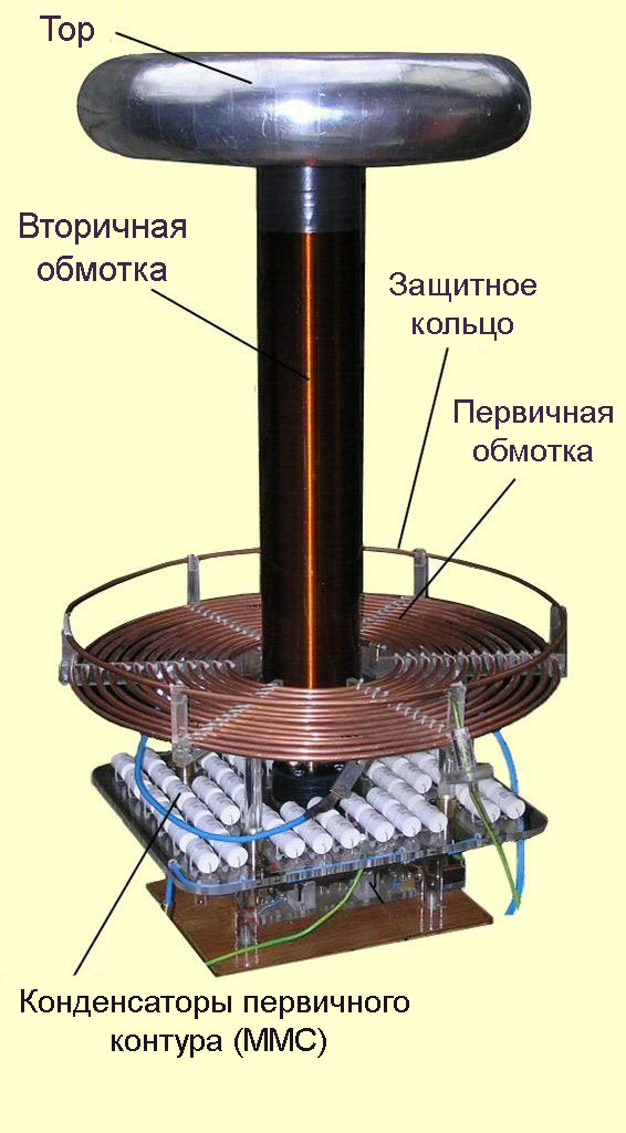
The Tesla transformer, the diagram of which will be presented below, consists of two coils, a toroid, a protective ring and, of course, grounding.

Tabletop CT sketch
It is necessary to consider each element separately:
- The primary coil is located at the very bottom. Power is supplied to it. It must be grounded. Made from low resistance metal;
- secondary coil. For winding, enameled copper wire of approximately 800 turns is used. This way the coils will not unravel or get scratched;
- toroid. This element reduces the resonant frequency, accumulates energy and increases the working field.
- protective ring. It is an open loop of copper wire. Set if the length of the streamer is greater than the length of the secondary winding;
- grounding If you turn on an ungrounded coil, streamers (current discharges) will not shoot into the air, but will create a closed ring.

CT drawing
Self-production
So, the simplest way to make a Tesla coil for dummies with your own hands. Often on the Internet you can see amounts exceeding the cost of a good smartphone, but in reality, a 12V transformer, which will make it possible to enjoy turning on the lamp without using an outlet, can be assembled from a heap of garage trash.

What should happen in the end?
You will need enameled copper wire. If you can’t find an enamel one, then you will additionally need regular nail polish. The wire diameter can be from 0.1 to 0.3 mm. To maintain the number of turns you will need about 200 meters. You can wind it on a regular PVC pipe with a diameter of 4 to 7 cm. Height is from 15 to 30 cm. You will also have to buy a transistor, for example, D13007, a pair of resistors and wires. It would be nice to get a computer cooler that will cool the transistor.
Now you can start assembling:
- cut 30 cm of pipe;
- wrap the wire around it. The turns should be as close to each other as possible. If the wire is not coated with enamel, varnish it at the end. From the top of the pipe, thread the end of the wire through the wall and bring it up so that it sticks out 2 cm above the installed pipe.;
- make a platform. A regular chipboard will do;
- you can make the first coil. You need to take a 6 mm copper pipe, bend it into three and a half turns and secure it to the frame. If the tube diameter is smaller, then there should be more turns. Its diameter should be 3 cm larger than the second coil. Attach to the frame. Immediately attach the second coil;
- There are quite a few ways to make a toroid. Copper tubes can be used. But it’s easier to take a regular aluminum corrugation and a metal crossbar for fastening to the protruding end of the wire. If the wire is too flimsy to hold the toroid, you can use a nail, like in the picture below;
- Don't forget about the protective ring. Although if one end of the primary circuit is grounded, it can be abandoned;
- When the design is ready, the transistor is connected according to the circuit, attached to a radiator or cooler, then you need to supply power and the installation is completed.

The first coil can be made flat, as in the picture
Many people use a regular Duracell crown to power the installation.

DIY Tesla transformer, simple circuit
Coil calculation
Calculation of CT is usually carried out during the manufacture of an industrial-sized transformer. For home experiments, it is enough to use the above recommendations.
The calculation itself will tell you the optimal number of turns for the secondary coil depending on the turns of the first, the inductance of each coil, the capacitance of the circuits and, most importantly, the required operating frequency of the transformer and the capacitance of the capacitor.

CT calculation example
Security measures
Once you have collected the CT, you need to take some precautions before launching. First, you need to check the wiring in the room where you plan to connect the transformer. Secondly, check the insulation of the windings.
It is also worth remembering the simplest precautions. The voltage of the secondary winding is on average 700A, 15A is already fatal for a person. Additionally, it is worth putting away all electrical appliances; if they get into the coil’s operating area, they are likely to burn out.
CT is a revolutionary discovery of its time, underestimated today. Today the Tesla transformer is used only for the entertainment of home electricians and in light shows. You can make a coil yourself using available materials. You will need a PVC pipe, several hundred meters of copper wire, a couple of meters of copper pipes, a transistor and a couple of resistors.
A Tesla coil is a high-frequency resonant transformer without a ferromagnetic core, which can be used to obtain high voltage on the secondary winding. Under the influence of high voltage in the air, an electrical breakdown occurs, similar to a lightning strike. The device was invented by Nikola Tesla, and bears his name.
According to the type of switching element of the primary circuit, Tesla coils are divided into spark (SGTC - Spark gap Tesla coil), transistor (SSTC - Solid state Tesla coil, DRSSTC - Dual resonant solid state Tesla coil). I will only consider spark coils, which are the simplest and most common. According to the method of charging the loop capacitor, spark coils are divided into 2 types: ACSGTC - Spark gap Tesla coil, and DCSGTC - Spark gap Tesla coil. In the first option, the capacitor is charged with an alternating voltage; in the second, a resonant charge is used with a constant voltage applied.
The coil itself is a structure of two windings and a torus. The secondary winding is cylindrical, wound on a dielectric pipe with copper winding wire, in one layer turn to turn, and usually has 500-1500 turns. The optimal ratio of the diameter and length of the winding is 1:3.5 – 1:6. To increase electrical and mechanical strength, the winding is coated with epoxy glue or polyurethane varnish. Typically, the dimensions of the secondary winding are determined based on the power of the power source, that is, the high-voltage transformer. Having determined the diameter of the winding, the length is found from the optimal ratio. Next, select the diameter of the winding wire so that the number of turns is approximately equal to the generally accepted value. Sewer plastic pipes are usually used as a dielectric pipe, but you can also make a homemade pipe using sheets of drawing paper and epoxy glue. Hereinafter we are talking about medium coils, with a power of 1 kW and a secondary winding diameter of 10 cm.
A hollow conductive torus, usually made of corrugated aluminum pipe, is installed at the upper end of the secondary winding pipe to remove hot gases. Basically, the diameter of the pipe is selected equal to the diameter of the secondary winding. The diameter of the torus is usually 0.5-0.9 times the length of the secondary winding. The torus has an electrical capacitance, which is determined by its geometric dimensions, and acts as a capacitor.
The primary winding is located at the lower base of the secondary winding, and has a spiral flat or conical shape. Typically consists of 5-20 turns of thick copper or aluminum wire. High-frequency currents flow in the winding, as a result of which the skin effect can have a significant influence. Due to the high frequency, the current is distributed predominantly in the surface layer of the conductor, thereby reducing the effective cross-sectional area of the conductor, which leads to an increase in active resistance and a decrease in the amplitude of electromagnetic oscillations. Therefore, the best option for making the primary winding would be a hollow copper tube or a flat wide strip. An open protective ring (Strike Ring) from the same conductor is sometimes installed above the primary winding along the outer diameter and grounded. The ring is designed to prevent discharges from entering the primary winding. The gap is necessary to prevent current flow through the ring, otherwise the magnetic field created by the induction current will weaken the magnetic field of the primary and secondary windings. The protective ring can be dispensed with by grounding one end of the primary winding, and the discharge will not harm the coil components.
The coupling coefficient between the windings depends on their relative position; the closer they are, the greater the coefficient. For spark coils, a typical coefficient value is K=0.1-0.3. The voltage on the secondary winding depends on it; the higher the coupling coefficient, the higher the voltage. But it is not recommended to increase the coupling coefficient above the norm, since discharges will begin to jump between the windings, damaging the secondary winding. 
The diagram shows the simplest version of a Tesla coil of the ACSGTC type.
The operating principle of a Tesla coil is based on the phenomenon of resonance of two inductively coupled oscillatory circuits. The primary oscillatory circuit consists of a capacitor C1, a primary winding L1, and is switched by a spark gap, resulting in a closed circuit. The secondary oscillatory circuit is formed by the secondary winding L2 and capacitor C2 (a toroid with capacitance), the lower end of the winding must be grounded. When the natural frequency of the primary oscillatory circuit coincides with the frequency of the secondary oscillatory circuit, a sharp increase in the amplitude of voltage and current in the secondary circuit occurs. At a sufficiently high voltage, electrical breakdown of the air occurs in the form of a discharge emanating from the torus. It is important to understand what a closed secondary circuit is. The secondary circuit current flows through the secondary winding L2 and capacitor C2 (torus), then through the air and ground (since the winding is grounded), the closed circuit can be described as follows: ground-winding-torus-discharge-ground. Thus, the exciting electrical discharges are part of the circuit current. If the grounding resistance is high, the discharges emanating from the torus will hit directly the secondary winding, which is not good, so you need to do high-quality grounding.
Once the dimensions of the secondary winding and torus have been determined, the natural frequency of oscillation of the secondary circuit can be calculated. Here we must take into account that the secondary winding, in addition to inductance, has some capacitance due to its considerable size, which must be taken into account when calculating; the winding capacitance must be added to the torus capacitance. Next, you need to estimate the parameters of the coil L1 and capacitor C1 of the primary circuit, so that the natural frequency of the primary circuit is close to the frequency of the secondary circuit. The capacitance of the primary circuit capacitor is usually 25-100 nF, based on this, the number of turns of the primary winding is calculated, on average it should be 5-20 turns. When making a winding, it is necessary to increase the number of turns compared to the calculated value in order to subsequently tune the coil to resonance. All these parameters can be calculated using standard formulas from a physics textbook; there are also books online on calculating the inductance of various coils. There are also special calculator programs for calculating all the parameters of the future Tesla coil.
The adjustment is carried out by changing the inductance of the primary winding, that is, one end of the winding is connected to the circuit, and the other is not connected anywhere. The second contact is made in the form of a clamp, which can be thrown from one turn to another, thereby not the entire winding is used, but only part of it, and the inductance and natural frequency of the primary circuit change accordingly. The tuning is carried out during preliminary launches of the coil; resonance is judged by the length of the discharged discharges. There is also a method for cold tuning the resonance using an RF generator and an oscilloscope or RF voltmeter, without the need to run the coil. It is necessary to note that the electric discharge has a capacitance, as a result of which the natural frequency of the secondary circuit may decrease slightly during operation of the coil. Grounding may also have a small effect on the secondary frequency.
The spark gap is a switching element in the primary oscillatory circuit. When an electrical breakdown of the spark gap occurs under the influence of high voltage, an arc is formed in it, which closes the circuit of the primary circuit, and high-frequency damped oscillations arise in it, during which the voltage on capacitor C1 gradually decreases. After the arc goes out, the loop capacitor C1 begins to charge again from the power source, and with the next breakdown of the spark gap, a new cycle of oscillations begins.
The arrester is divided into two types: static and rotating. A static discharger consists of two closely spaced electrodes, the distance between which is adjusted so that an electrical breakdown between them occurs at a time when the capacitor C1 is charged to the highest voltage, or slightly less than the maximum. The approximate distance between the electrodes is determined based on the electrical strength of air, which is about 3 kV/mm under standard environmental conditions, and also depends on the shape of the electrodes. For alternating mains voltage, the response frequency of the static discharge (BPS - beats per second) will be 100 Hz.
A rotating spark gap (RSG - Rotary spark gap) is made on the basis of an electric motor, on the shaft of which a disk with electrodes is mounted; static electrodes are installed on each side of the disk, thus, when the disk rotates, all the electrodes of the disk will fly between the static electrodes. The distance between the electrodes is kept to a minimum. In this option, you can adjust the switching frequency over a wide range by controlling the electric motor, which gives more opportunities for tuning and controlling the coil. The motor housing must be grounded to protect the motor winding from breakdown when exposed to a high-voltage discharge.
Capacitor assemblies (MMC - Multi Mini Capacitor) of series and parallel connected high-voltage high-frequency capacitors are used as loop capacitor C1. Typically, ceramic capacitors of the KVI-3 type are used, as well as film capacitors K78-2. Recently, a transition to paper capacitors of the K75-25 type has been planned, which have shown good performance. For reliability, the rated voltage of the capacitor assembly should be 1.5-2 times the amplitude voltage of the power source. To protect capacitors from overvoltage (high-frequency pulses), an air gap is installed parallel to the entire assembly. The spark gap can be two small electrodes.
A high-voltage transformer T1, or several series- or parallel-connected transformers, is used as a power source for charging the capacitors. Basically, novice Tesla builders use a microwave oven transformer (MOT - Microwave Oven Transformer), the output alternating voltage of which is ~2.2 kV, power of about 800 W. Depending on the rated voltage of the loop capacitor, MOTs are connected in series from 2 to 4 pieces. The use of only one transformer is not advisable, since due to the small output voltage the gap in the spark gap will be very small, resulting in unstable results of the coil operation. The motors have the disadvantages of poor electrical strength, are not designed for long-term operation, and get very hot under heavy loads, so they often fail. It is more reasonable to use special oil transformers such as OM, OMP, OMG, which have an output voltage of 6.3 kV, 10 kV, and a power of 4 kW, 10 kW. You can also make a homemade high-voltage transformer. When working with high-voltage transformers, one should not forget about safety precautions; high voltage is dangerous to life; the transformer housing must be grounded. If necessary, an autotransformer can be installed in series with the primary winding of the transformer to regulate the charging voltage of the loop capacitor. The power of the autotransformer must be no less than the power of transformer T1.
The inductor Ld in the power circuit is necessary to limit the short circuit current of the transformer in the event of breakdown of the spark gap. Most often, the inductor is located in the secondary winding circuit of transformer T1. Due to the high voltage, the required inductance of the inductor can take large values from units to tens of Henry. In this embodiment, it must have sufficient electrical strength. With the same success, the inductor can be installed in series with the primary winding of the transformer; accordingly, high electrical strength is not required here, the required inductance is an order of magnitude lower, and amounts to tens, hundreds of millihenries. The diameter of the winding wire must be no less than the diameter of the wire of the primary winding of the transformer. The inductance of the inductor is calculated from the formula for the dependence of inductive reactance on the frequency of alternating current.
The low-pass filter (LPF) is designed to prevent the penetration of high-frequency pulses of the primary circuit into the inductor circuit and the secondary winding of the transformer, that is, to protect them. The filter can be L-shaped or U-shaped. The cutoff frequency of the filter is chosen an order of magnitude lower than the resonant frequency of the oscillatory circuits of the coil, but the cutoff frequency must be much higher than the response frequency of the spark gap. 
When resonantly charging a loop capacitor (coil type - DCSGTC), a constant voltage is used, unlike ACSGTC. The voltage of the secondary winding of transformer T1 is rectified using a diode bridge and smoothed with capacitor St. The capacitance of the capacitor should be an order of magnitude greater than the capacitance of loop capacitor C1 to reduce DC voltage ripple. The capacitance value is usually 1-5 µF; for reliability, the rated voltage is chosen to be 1.5-2 times the amplitude rectified voltage. Instead of one capacitor, you can use capacitor assemblies, preferably not forgetting about equalizing resistors when connecting several capacitors in series.
High-voltage diode columns of the KTs201 type and others are used in series as bridge diodes. The rated current of the diode columns must be greater than the rated current of the secondary winding of the transformer. The reverse voltage of the diode columns depends on the rectification circuit; for reliability reasons, the reverse voltage of the diodes should be 2 times the amplitude value of the voltage. It is possible to manufacture homemade diode posts by connecting conventional rectifier diodes in series (for example 1N5408, Urev = 1000 V, In = 3 A), using equalizing resistors.
Instead of the standard rectification and smoothing circuit, you can assemble a voltage doubler from two diode columns and two capacitors.
The operating principle of the resonant charge circuit is based on the phenomenon of self-inductance of the inductor Ld, as well as the use of a cut-off diode VDо. At the moment when capacitor C1 is discharged, current begins to flow through the inductor, increasing according to a sinusoidal law, while energy in the form of a magnetic field accumulates in the inductor, and the capacitor is charged, accumulating energy in the form of an electric field. The voltage across the capacitor increases to the voltage of the power supply, while the maximum current flows through the inductor, and the voltage drop across it is zero. In this case, the current cannot stop instantly, and continues to flow in the same direction due to the presence of self-induction of the inductor. Charging of the capacitor continues until the power source voltage is doubled. A cut-off diode is necessary to prevent energy from flowing from the capacitor back to the power source, since a potential difference appears between the capacitor and the power source equal to the voltage of the power source. In fact, the voltage across the capacitor does not reach double the value due to the presence of a voltage drop across the diode column.
The use of a resonant charge makes it possible to more efficiently and evenly transfer energy to the primary circuit, while to obtain the same result (over the discharge length), DCSGTC requires less power from the power source (transformer T1) than ACSGTC. The discharges acquire a characteristic smooth bend due to a stable supply voltage, in contrast to ACSGTC, where the next approach of the electrodes in the RSG can occur in time at any section of the sinusoidal voltage, including contact with zero or low voltage and, as a result, a variable discharge length (ragged discharge).
The picture below shows the formulas for calculating the parameters of a Tesla coil: 
I suggest you familiarize yourself with my construction experience.

electromagnetic field of Tesla coil
Introduction……………………………………………………..………......2 pages.
Theoretical part of Nikola Tesla and his inventions…………………..…………………5 pages. Installation diagram of the Tesla coil…………………………. ........8 pp. Practical part Sociological survey among students of the Federal Secondary School No. 5...... 8 pp. Assembling a Tesla coil.................................... …………...9 pp. Calculation of the main characteristics of the manufactured Tesla coil 9 pp. Experimental experiments in the use of the Tesla coil….……11 pp. Modern application of Tesla’s ideas…………………………..13 p. Photo and video report of the study………………..14 p.
Conclusion……………………………………………………………….……..................15 p.
References……………………………………………………….……………….…..16 pages.
Appendices…………………………………………………………….…….……….…..18 p.
Introduction
I could split the globe, but never
I won't do this.
My main goal was to point out new phenomena
and spread ideas that will become
starting points for new research.
Nikola Tesla
“I have finally succeeded in creating discharges whose power greatly exceeds that of lightning. Are you familiar with the expression “you can’t jump over your head”? This is a misconception. A person can do anything." In the International Year of Light and Light Technologies, I think it is worth remembering the legendary personality Nikola Tesla, and the meaning of some of his inventions is still being debated to this day. A lot of different things have been said about him, but most people, including me, are unanimous in their opinion - Tesla did a lot for the development of science and technology for his time. Many of his patents have come to life, but some still remain beyond understanding. But Tesla's main achievements can be considered research into the nature of electricity. Especially high voltage. Tesla amazed his acquaintances and colleagues with amazing experiments in which, without difficulty or fear, he controlled high-voltage generators that produced hundreds and sometimes millions of volts. Back in the 1900s, Tesla could transmit current over vast distances without wires, obtaining a current of 100 million amperes and a voltage of 10 thousand volts. And maintain such characteristics for any necessary time. For those who lived next to him, the world changed, turned into a fairy-tale space where nothing should be surprised. Northern lights flashed over the entire Atlantic, ordinary butterflies turned into bright fireflies, ball lightning was easily taken out of suitcases and used to illuminate living rooms. His experiments always balanced on the brink of evil and good. The fall of the Tunguska meteorite, the earthquake in New York, the testing of monstrous weapons capable of instantly destroying entire armies - this is what else, besides luminous butterflies, is attributed to Tesla's experiments. It was he who served for many science fiction writers as the image of a mad professor whose inventions threaten to destroy the entire planet. In fact, we know nothing about what kind of person Nikola Tesla was, what kind of hero he should become for biographers, good or bad.

Experimental physics is of great importance in the development of science. It's better to see once than to hear a hundred times. No one will argue that experiment is a powerful impetus to understanding the essence of phenomena in nature. You can admire nature without knowing physics. But to understand it and see what is hidden behind the external images of phenomena is possible only with the help of exact science and experimentation. Today we can say with confidence that only a fait accompli is accurate in nature, that is, experience or experiment, or the results of a natural process, the course of which does not depend on man. Only the result obtained through one or another action remains unshakable. As I already said, this is the only certainty in the hypothesis. Everyone knows that any hypothesis rests on three pillars: the result of the experiment, its description and the conclusion, which is based on recognized stereotypes (Appendix 1).
Experiments with electricity. If you think about it, what else can you discover and experiment with? After all, now humanity has long been unable to imagine its existence without electricity. All household appliances, our entire industry, and medical devices operate with it. One thing is true, the current itself reaches us, alas, only through wires. This is all very far from what Nikola Tesla could do more than 100 years ago, and what modern physics still cannot explain. Modern physics is simply not able to achieve such indicators. He turned the electric motor on and off remotely, and the light bulbs in his hands lit up by themselves. Modern scientists have only reached the level of 30 million amperes (with the explosion of an electromagnetic bomb), and 300 million with a thermonuclear reaction - and even then, for a split second.
The relevance lies in the fact that in our time, enthusiasts and scientists around the world are trying to repeat the experiments of the brilliant scientist and find their application. I won’t go into mysticism, I tried to do something spectacular according to Tesla’s “recipes”. This is a Tesla coil. Having seen it once, you will never forget this incredible and amazing sight.
Object of study: Tesla coil.
Subject of research: electromagnetic field of a Tesla coil, high-frequency discharges in gas.
The purpose of the research: to manufacture a high-frequency Tesla coil and conduct experiments based on the assembled operating installation.
The object, subject and purpose of the study led to the formulation of the following hypothesis: an electromagnetic field of enormous intensity is formed around the Tesla coil, capable of transmitting electric current wirelessly.
Study the literature on the research problem. Get acquainted with the history of the invention and the principle of operation of the Tesla coil. Finding parts and making a Tesla coil. Conduct a sociological survey among students in grades 7-11 at Fedorovskaya Secondary School No. 5. Conduct calculations of the characteristics of the Tesla coil and experiments demonstrating its operation. Prepare a photo and video report on the work done for the benefit of students in grades 9-11.
Research methods:
Empirical: observation of high-frequency electrical discharges in a gaseous environment, research, experiment. Theoretical: Tesla coil design, literature analysis, statistical processing of results.
Research stages:
Theoretical part. Studying the literature on the research problem. Practical part. Making a Tesla Transformer and Demonstrating the Incredible Electromagnetic Field Properties of a Tesla Coil
Novelty: lies in the fact that, like many experimental inventors, I
For the first time, having studied, he assembled a Tesla coil and, as part of the International Year of Light and Light Technologies 2015, conducted a series of experiments and thereby showed the significance of Tesla’s works.
Practical significance: the result of the work is educational in nature, this will increase the interest of students in in-depth study of subjects such as physics, young researchers - to, and perhaps for some will determine the area of further activity.
Theoretical part
I.1.Nikola Tesla and his inventions
What do we know about Nikola Tesla and his works? Tesla's activities are indifferent and uninteresting to the common man. In schools and institutes, Tesla is mentioned only when they talk about the inductance unit of the same name. This is how society “thanked” the great practitioner for all the contributions he made to the development of electrical engineering. All his activities are shrouded in a veil of mystery, and many simply consider him a scientific charlatan. Let's try to consider the significance of Tesla's “legacy”. NIKOLA TESLA is an inventor in the field of electrical and radio engineering, engineer, and physicist. Born and raised in Austria-Hungary, in subsequent years he worked mainly in France and the USA. He is also known as a supporter of the existence of ether: his numerous experiments are known, the purpose of which was to show the presence of ether as a special form of matter that can be used in technology. if named magnetic flux density. Contemporary biographers considered Tesla "the man who invented the 20th century" and the "patron saint" of modern electricity. Tesla's early work paved the way for modern electrical engineering, and his early discoveries were innovative. Until 1882, Tesla worked as an electrical engineer for the government telegraph company in Budapest. In February 1882, Tesla figured out how to use a phenomenon that would later become known as the rotating magnetic field in an electric motor. Tesla worked on making a model of an asynchronous electric motor, and in 1883 he demonstrated the operation of the engine in the city hall of Strasbourg. 1884 Tesla arrived in New York. He took a job with Thomas Edison as an engineer repairing electric motors and DC generators. Edison perceived Tesla's new ideas rather coldly and increasingly openly expressed disapproval of the direction of the inventor's personal research. In the spring of 1885, Edison promised Tesla 50 thousand dollars if he could constructively improve the direct current electric machines invented by Edison. Nikola actively got to work and soon introduced 24 varieties of Edison's machine, a new switch and regulator, which significantly improved performance. Having approved all the improvements, in response to a question about the reward, Edison refused Tesla. Offended, Tesla immediately quit. From 1888 to 1895, Tesla researched magnetic fields and high frequencies in his laboratory. These years were the most fruitful; it was then that he patented most of his inventions. At the end of 1896, Tesla achieved radio signal transmission over a distance of 48 km. Tesla set up a small laboratory in Colorado Springs. To study thunderstorms, Tesla designed a special device, which was a transformer, one end of the primary winding of which was grounded, and the other was connected to a metal ball on a rod extending upward. A sensitive self-tuning device connected to a recording device was connected to the secondary winding. This device allowed Nikola Tesla to study changes in the Earth's potential, including the effect of standing electromagnetic waves caused by lightning discharges in the Earth's atmosphere. Observations led the inventor to think about the possibility of transmitting electricity wirelessly over long distances. Tesla's next experiment was aimed at exploring the possibility of independently creating a standing electromagnetic wave. The turns of the primary winding were wound on the huge base of the transformer. The secondary winding was connected to a 60-meter mast and ended with a copper ball of a meter in diameter. When an alternating voltage of several thousand volts was passed through the primary coil, a current with a voltage of several million volts and a frequency of up to 150 thousand hertz arose in the secondary coil. During the experiment, lightning-like discharges were recorded emanating from a metal ball. The length of some discharges reached almost 4.5 meters, and thunder was heard at a distance of up to 24 km. Based on the experiment, Tesla concluded that the device allowed him to generate standing waves that propagated spherically from the transmitter, and then converged with increasing intensity at a diametrically opposite point on the globe, somewhere near the islands of Amsterdam and Saint-Paul in the Indian Ocean. In 1917, Tesla proposed the principle of operation of a device for radio detection of submarines. One of his most famous inventions is the Tesla Transformer (coil). The Tesla transformer, also known as the Tesla coil, is a device invented by Nikola Tesla and bearing his name. It is a resonant transformer that produces high voltage and high frequency. The device was patented in 1896 as “Apparatus for producing electric currents of high frequency and potential.” The simplest Tesla transformer consists of two coils - primary and secondary, as well as a spark gap, capacitors, a toroid and a terminal. The primary coil usually contains several turns of large diameter wire or copper tubing, and the secondary coil usually contains about 1000 turns of smaller diameter wire. The primary coil, together with the capacitor, forms an oscillatory circuit, which includes a nonlinear element - a spark gap. The secondary coil also forms an oscillatory circuit, where the role of a capacitor is mainly played by the capacitance of the toroid and the own interturn capacitance of the coil itself. The secondary winding is often coated with a layer of epoxy resin or varnish to prevent electrical breakdown. Thus, the Tesla transformer consists of two connected oscillatory circuits, which determines its remarkable properties and is its main difference from conventional transformers. After the breakdown voltage is reached between the electrodes of the arrester, an avalanche-like electrical breakdown of the gas occurs in it. The capacitor is discharged through a spark gap onto the coil. Therefore, the circuit of the oscillatory circuit, consisting of a primary coil and a capacitor, remains closed through the spark gap, and high-frequency oscillations arise in it. Resonant oscillations occur in the secondary circuit, which leads to the appearance of high voltage at the terminal. In all types of Tesla transformers, the main element of the transformer - the primary and secondary circuits - remains unchanged. However, one of its parts, the high-frequency oscillation generator, can have a different design. |
I.2. Tesla coil installation diagram
The Tesla resonant generator, coil or transformer is a brilliant invention of the great Serbian inventor, physicist and engineer. A transformer consists of two coils that do not have a common iron core. The primary winding must have at least a dozen turns of thick wire. At least 1000 turns are already wound on the secondary one. Please note that the Tesla coil has a transformation ratio that is 10-50 times greater than the ratio of the number of turns on the second winding to the first. The output voltage of such a transformer can exceed several million volts. It is this circumstance that ensures the occurrence of spectacular discharges, the length of which can reach several meters at once. It is very important: both the capacitor and the primary winding must ultimately form a specific oscillatory circuit that enters into a state of resonance with the secondary winding. K The Tesla coil installation diagram assumes a current strength of 5-8 A. The maximum value of this value, which still leaves a chance of survival, is 10 A. So when working, do not forget for a second about the simplest precautions.
On the Internet you can find different options for manufacturing high-frequency and voltage sources. We chose one of the schemes (Appendix 2), which consists of:
Power supply (220V - 24V) Variable resistor Resistor Primary coil (9 turns) Secondary coil (1000 turns) Heatsink transistor (MJE 13007) Practical part
II.1 Sociological survey among students in grades 7-11 of Federal Secondary School No. 5
325 people took part in the survey. Questions were asked:
1. Have you heard about the inventions of Nikola Tesla (Tesla coil)?
2. Would you like to see a series of experiments using a Tesla coil?
After processing the results, the result is as follows: 176 students heard about Tesla’s inventions, 156 students did not. 97 people saw videos of experiments on the Internet, 228 have no idea what a coil looks like or its use. All 325 students would like to see the result of the research work and a series of experiments using the Tesla coil.
II.2 Tesla coil assembly
Let us turn to the device that is now known as the Tesla transformer (coil). All over the world, Tesla manufacturers annually reproduce its numerous modifications. The main goal of most of these Tesla radio amateurs is to obtain light and sound effects achieved in experiments with high voltage, which is present at the output of the high-voltage coil of the Tesla transformer (TT). Many are also attracted by Tesla's ideas for generating high-power energy, and even more attractive is the attempt to create an "over-unit" (SE) device based on CT. This is the realm of alternative science.
I assembled the installation myself based on the diagram (Appendix 2, Fig. 1, 2, 3, 4, 5). A coil wound on a frame from a plastic (plumbing) pipe with a diameter of 5 cm. The primary winding contains only 9 turns, a wire with a diameter of 1.5 mm, a single-core copper wire in rubber insulation was used. The secondary winding contains 1000 turns of 0.1 mm wire. The secondary winding is wound neatly, turn to turn. This device produces high voltage at high frequency. A Tesla coil is a demonstration generator of high-frequency, high-voltage currents. The device can be used to wirelessly transmit electric current over long distances. During the study, I will demonstrate the action of the Tesla coil I made (Appendix 3, Fig. 6).
II.3 Calculation of the main characteristics of the manufactured Tesla coil
- EMF: 24 V. Two batteries from a screwdriver, 12 V each. Resistance: R=50075 Ohm. R= R1+ R2 (series connection) It is considered necessary to neglect the internal resistance of the source, wires, windings. 1) Variable resistor (Rheostat) 50 KOhm. 2) Resistor 75 Ohm. Current: 0.5 mA. Calculated from Ohm's law for a complete circuit I= EMF/ R+r
and checked with an ammeter.
- Oscillation frequency: 200 MHz. Calculations were made using CircutLab.

- Input voltage: 24 V. Output voltage: ~2666.7 V. Transformation ratio is a value equal to the ratio of voltages in the primary and secondary windings of the transformer.
K=U1/U2=N1/N2, where
N1 - number of turns on the primary winding of the transformer
N2 is the number of turns on the secondary winding of the transformer
subject to K< 1, U2 >U1, N2> N1 – step-up transformer
provided K >1, U1> U2, N1> N2 – step-down transformer
K=U1/U2 =24/2667=0.009< 1 повышающий трансформатор
K= N1/N2 =9/1000=0.009< 1 повышающий трансформатор
Let's plot the dependence of the output voltage on the number of turns of the secondary coil (Appendix 4). The diagram shows that the greater the number of turns on the secondary winding, the greater the output voltage of the coil.
CONCLUSION: coil discharges are not dangerous to the human body during short-term exposure, since the current strength is negligible, and the frequency and voltage are too high.
II.4 Experimental experiments using the Tesla coil
With a finished Tesla coil, you can conduct a number of interesting experiments, observing safety rules. To conduct experiments, you must have very reliable wiring, otherwise disaster will not be avoided. You can even touch the high voltage output coil with a piece of metal. Why does nothing happen to the experimenter when he touches a voltage source of 250,000 V at a high frequency of 500 kHz? The answer is simple. Nikola Tesla also discovered this “terrible” secret - high-frequency currents at high voltages are safe.
During operation, the Tesla coil creates beautiful effects associated with the formation of various types of gas discharges. Many people collect Tesla coils in order to look at these impressive, beautiful phenomena. In general, a Tesla coil produces several types of discharges:
- Spark is a spark discharge. There is also a special type of spark discharge - a sliding spark discharge. Streamers are dimly glowing thin branched channels that contain ionized gas atoms and free electrons split off from them. It flows from the coil terminal directly into the air without going into the ground. A streamer is, in fact, visible ionization of air (glow of ions) created by the high-voltage field of a transformer. Corona discharge is the glow of air ions in a high voltage electric field. Creates a beautiful bluish glow around explosive parts of a structure with a strong surface curvature. Arc discharge - occurs in many cases. For example, with sufficient transformer power, if a grounded object is brought close to its terminal, an arc may light up between it and the terminal
It is interesting to note that some ionic chemicals applied to the discharge terminal can change the color of the discharge. For example, sodium ions change the normal color of spark to orange, boron to green, manganese to blue, lithium to crimson.
The operation of a resonant transformer is accompanied by a characteristic electrical crackling sound. This appearance is associated with the transformation of streamers into spark channels, which is accompanied by a sharp increase in the current strength and energy released in them.
Using a manufactured Tesla coil, I demonstrate many beautiful and impressive experiments. Demonstrations using a transformer. Let's observe the discharges.
Demonstration No. 1. Demonstration of gas discharges. Streamer, spark, arc discharge.
Equipment: Tesla coil (transformer), screwdriver.
When the coil is turned on, a discharge begins to emerge from the terminal, which is 6-7 mm long. (Appendix 5, Fig. 7, 8).
Demonstration No. 2. Demonstration of a glow discharge. The glow of spectral tubes filled with inert gases: helium, neon.
Equipment: Tesla coil (transformer), set of spectral tubes.
When we bring these lamps to the Tesla coil, we will observe how the gas with which the tubes are filled will glow (Appendix 6, Fig. 9, 10,11).
Demonstration No. 3. Demonstration of discharge in a fluorescent lamp and a fluorescent lamp (FLL).
Equipment: Tesla coil (transformer), fluorescent lamp, fluorescent lamp.
A discharge is observed in the fluorescent lamp (Appendix 7, Fig. 12, 13).
Demonstration No. 4. Experiment with rulers.
Equipment: Tesla coil (transformer), metal ruler, wooden ruler.
When a metal ruler is introduced into the discharge, the streamer hits it, while the ruler remains cold. When a wooden ruler is placed into a discharge, the streamer quickly covers its surface and after a few seconds the ruler lights up (Appendix 8, Fig. 14, 15, 16).
Demonstration No. 5. Experiment with paper.
Equipment: Tesla coil (transformer), paper.
When introducing paper into a discharge, the streamer quickly covers its surface and after a few seconds the paper flares up (Appendix 9, Fig. 17).
Demonstration No. 6. Experiment with a whisk.
We branch the wires and solder them to the terminal in advance (Appendix 10, Fig. 18).
Demonstration No. 7. Plasma tree.
Equipment: Tesla coil (transformer), thin stranded wire.
We branch the wires from the wire, which has been previously stripped of insulation, and screw it to the terminal (Appendix 11, Fig. 19,20, 21, 22).
Demonstration No. 8. Ion motor.
Equipment: Tesla coil (transformer), cross plate.
We screw the needle to the transformer terminal and install a cross plate on top in the center. After turning on the coil, streamers begin to emerge from the 4 ends of the cross and under their action the plate begins to rotate (Appendix 12, Fig. 23).
II.5 Modern application of Tesla's ideas
Alternating current is the main method of transmitting electricity over long distances.
- Electric generators are the main elements in generating electricity at hydroelectric power plants, thermal power plants, etc. Electric motors, first created by Nikola Tesla, are used in all modern machine tools, electric trains, electric cars, trams, trolleybuses. Radio-controlled robotics have become widespread not only in children's toys and wireless television and computer devices (control panels), but also in the military sphere, in the civilian sphere, in matters of military, civil and internal, as well as external security of countries, etc. Wireless chargers are starting to be used to charge mobile phones or laptops.
- Alternating current, pioneered by Tesla, is the primary way to transmit electricity over long distances.
- Original modern anti-theft agents for cars work on the same principle as coils. Use for entertainment purposes and shows. The transformer was used by Tesla to generate and propagate electrical oscillations to control devices over a distance without wires, transmit data wirelessly, and transmit energy wirelessly. In films, episodes are based on demonstrations of the Tesla transformer, in computer games. At the beginning of the 20th century, the Tesla transformer also found popular use in medicine. Patients were treated with weak high-frequency currents, which, flowing through a thin layer of the skin surface, did not cause harm to internal organs, while providing a “tonic” and “healing” effect. It is used to ignite gas discharge lamps and to search for leaks in systems. Its main use today is cognitive and aesthetic. This is mainly due to significant difficulties when it is necessary to control the selection of high-voltage power, or even more so, transfer it to a distance from the transformer, since in this case the device inevitably goes out of resonance, and the quality factor of the secondary circuit is also significantly reduced.
Conclusion: it is incorrect to assume that the Tesla coil does not have wide practical applications. The examples I listed above clearly demonstrate this. However, its main use today is cognitive and aesthetic (Appendix 13, Fig. 24).
II.6. Photo and video report of the study
Attached is a photo report, a video report is attached to the work on electronic media. Booklet-memo “Modern application of Tesla’s ideas” (Appendix 14).
Conclusion
One of the brightest, most interesting and extraordinary personalities among physicists is Nikola Tesla. For some reason, he is not much favored on the pages of school physics textbooks, although without his works, discoveries and inventions it is difficult to imagine the existence of seemingly ordinary things, such as, for example, the presence of electric current in our sockets. Like Lomonosov, Nikola Tesla was ahead of his time and did not receive the recognition he deserved during his lifetime, however, to this day his works are not appreciated.
Tesla managed to combine the properties of a transformer and the phenomenon of resonance in one device. This is how the famous resonance transformer was created, which played a huge role in the development of many branches of electrical engineering and radio engineering and is widely known as the “Tesla transformer”.
The Tesla transformer (coil) is an amazing device that allows you to obtain a powerful intense flow of field emission in an extremely economical way. However, its unique properties and beneficial applications are far from being exhausted.
Undoubtedly, Nikola Tesla is an interesting figure from the point of view of the prospect of using his unconventional ideas in practice. The Serbian genius managed to leave a noticeable mark on the history of science and technology.
His engineering developments have found application in the field of electrical engineering, cybernetics, and medicine. The activities of the inventor are shrouded in mystical stories, among which one must choose those that contain true information, actual historical facts, scientific achievements and concrete results.
The issues that Nikola Tesla dealt with remain relevant today. Their consideration allows creative engineers and students of physics to take a broader look at the problems of modern science, abandon templates, learn to distinguish truth from fiction, generalize and structure material. Therefore, the views of N. Tesla can be considered relevant today not only for research in the field of the history of science and technology, but as a fairly effective means of search work, the invention of processes and the use of new technologies.
As a result of my research, the hypothesis was confirmed: an electromagnetic field of enormous intensity is formed around the Tesla coil, capable of transmitting electric current wirelessly:
- light bulbs filled with inert gas glow near the coil, therefore, there really is a high-intensity electromagnetic field around the installation; the light bulbs lit up by themselves in my hands at a certain distance, which means that electric current can be transmitted wirelessly.
It is necessary to note one more important thing: the effect of this installation on a person: as you noticed during work, I was not shocked: high-frequency currents that pass through the surface of the human body do not harm it, on the contrary, they have a tonic and healing effect, this is even used in modern medicine (from popular science literature). However, it should be noted that the electrical discharges that you saw have a high temperature, so it is not recommended to catch lightning with your hands for a long time!
Nikola Tesla laid the foundations of a new civilization of the third millennium and his role needs to be reassessed. Only the future will provide a real explanation for Tesla's phenomenon.
A transformer that increases voltage and frequency many times is called a Tesla transformer. Energy-saving and fluorescent lamps, picture tubes of old TVs, charging batteries from a distance and much more were created thanks to the operating principle of this device. Let’s not exclude its use for entertainment purposes, because the “Tesla transformer” is capable of creating beautiful purple discharges - streamers reminiscent of lightning (Fig. 1). During operation, an electromagnetic field is formed that can affect electronic devices and even the human body, and during discharges in the air a chemical process occurs with the release of ozone. To make a Tesla transformer with your own hands, you do not need to have extensive knowledge in the field of electronics, just follow this article.
Components and operating principle
All Tesla transformers, due to a similar operating principle, consist of the same blocks:
- Power supply.
- Primary circuit.

The power supply provides the primary circuit with voltage of the required magnitude and type. The primary circuit creates high-frequency oscillations that generate resonant oscillations in the secondary circuit. As a result, a current of high voltage and frequency is formed on the secondary winding, which tends to create an electrical circuit through the air - a streamer is formed.
The choice of primary circuit determines the type of Tesla coil, power source and size of the streamer. Let's focus on the semiconductor type. It features a simple circuit with accessible parts and a low supply voltage.
Selection of materials and parts
We will search and select parts for each of the above structural units:


After winding, we insulate the secondary coil with paint, varnish or other dielectric. This will prevent the streamer from getting into it.
Terminal – additional capacity of the secondary circuit, connected in series. For small streamers it is not necessary. It is enough to bring the end of the coil up 0.5–5 cm.
After we have collected all the necessary parts for the Tesla coil, we begin to assemble the structure with our own hands.
Design and assembly
We carry out the assembly according to the simplest scheme in Figure 4.

We install the power supply separately. The parts can be assembled by hanging installation, the main thing is to avoid short circuits between the contacts.
When connecting a transistor, it is important not to mix up the contacts (Fig. 5).

To do this, we check the diagram. We tightly screw the radiator to the transistor body.
Assemble the circuit on a dielectric substrate: a piece of plywood, a plastic tray, a wooden box, etc. Separate the circuit from the coils with a dielectric plate or board with a miniature hole for the wires.
We secure the primary winding so as to prevent it from falling and touching the secondary winding. In the center of the primary winding we leave space for the secondary coil, taking into account the fact that the optimal distance between them is 1 cm. It is not necessary to use a frame - a reliable fastening is enough.
We install and secure the secondary winding. We make the necessary connections according to the diagram. You can see the operation of the manufactured Tesla transformer in the video below.
Switching on, checking and adjusting
Before turning on, move electronic devices away from the test site to prevent damage. Remember electrical safety! To launch successfully, perform the following steps in order:
- We set the variable resistor to the middle position. When applying power, make sure there is no damage.
- Visually check the presence of the streamer. If it is missing, we bring a fluorescent light bulb or incandescent lamp to the secondary coil. The glow of the lamp confirms the functionality of the “Tesla transformer” and the presence of an electromagnetic field.
- If the device does not work, first of all we swap the leads of the primary coil, and only then we check the transistor for breakdown.
- When you turn it on for the first time, monitor the temperature of the transistor; if necessary, connect additional cooling.
Distinctive features of the powerful Tesla transformer are high voltage, large dimensions of the device and the method of producing resonant oscillations. Let's talk a little about how it works and how to make a Tesla spark-type transformer.
The primary circuit operates on alternating voltage. When turned on, the capacitor charges. As soon as the capacitor is charged to the maximum, a breakdown of the spark gap occurs - a device of two conductors with a spark gap filled with air or gas. After the breakdown, a series circuit of a capacitor and a primary coil is formed, called an LC circuit. It is this circuit that creates high-frequency oscillations, which create resonant oscillations and enormous voltage in the secondary circuit (Fig. 6).

If you have the necessary parts, you can assemble a powerful Tesla transformer with your own hands, even at home. To do this, it is enough to make changes to the low-power circuit:
- Increase the diameters of the coils and the cross-section of the wire by 1.1 - 2.5 times.
- Add a toroid-shaped terminal.
- Change the DC voltage source to an alternating one with a high boost factor that produces a voltage of 3–5 kV.
- Change the primary circuit according to the diagram in Figure 6.
- Add reliable grounding.
Tesla spark transformers can reach a power of up to 4.5 kW, therefore creating large-sized streamers. The best effect is obtained when the frequencies of both circuits are equal. This can be realized by calculating parts in special programs - vsTesla, inca and others. You can download one of the Russian-language programs from the link: http://ntesla.at.ua/_fr/1/6977608.zip.

"The Man Who Invented the 20th Century!" - this is what modern biographers call Tesla, and they do this without any exaggeration. He gained his fame thanks to his progressive views and the ability to prove their validity. Tesla conducted dangerous experiments in the name of science, and in certain circles is considered a figure associated with mysticism. In the latter case, most likely, we are dealing with speculation, but what is known for sure is that Nikola Tesla’s inventions contributed to progress throughout the world.
Nikola Tesla's legacy
First, let's look at inventions that are important from a scientific point of view, but rarely encountered in the everyday life of modern people.
We will talk about one of Nikola’s most famous and spectacular inventions. A Tesla coil is a type of resonant transformer circuit. This device was used to produce high voltage high frequency.
 The Tesla coil was one of the tools for studying the nature of electric current and the possibilities of its use
 Tesla used coils during innovative experiments in the field of:
- electric lighting;
- phosphorescence;
- x-ray generation;
- high frequency alternating current;
- electrotherapy;
- radio engineering;
- transmitting electrical energy without wires.

By the way, Nikola Tesla was one of those people who predicted the emergence of the Internet and modern gadgets.
The Tesla coil is an early predecessor (along with the induction coil) of a more modern device called a flyback transformer. It provides the voltage needed to power the cathode ray tube of televisions and computer monitors. Versions of this coil are widely used today in radio, television and other electronic equipment.
The coil can be seen in all its glory in science museums or at special shows.
A Tesla coil in action is always a spectacle:
This structure, also known as the Tesla Tower, was built to enable wireless telecommunications and demonstrate the possibility of transmitting electrical power without wires.

According to Tesla's idea, the Wardenclyffe Tower was supposed to be a step towards the creation Worldwide Wireless System. His plans were to install several dozen transceiver stations around the world. Thus, there would be no need to use high-voltage power lines. That is, in fact, we would have one global power plant. By the way, Tesla was able to transmit electricity “through the air” from one coil to another, so his ambitions were not unfounded.
 Today Wardenclyffe is a closed facility
 The Wardenclyffe project required large capital investments and received the support of influential investors in the initial stages. However, when work on the construction of the tower was almost completed, Tesla lost his funding and found himself on the brink of bankruptcy. And all because Wardenclyffe could be a prerequisite for free supplies of electricity throughout the world, and this could ruin some investors whose business was tied to the sale of electricity.
Fans of various conspiracy theories connect the fall of the Tunguska meteorite in Siberia and Tesla’s experiments with the Tower.
X-rays
Wilhelm Roentgen officially discovered the radiation named after him on November 8, 1895. But in fact, Nikola Tesla was the first to observe this phenomenon. Back in 1887, he began conducting research using vacuum tubes. During his experiments, Tesla recorded “special rays” that could “transparent” objects. At first, the scientist did not attach much importance to this phenomenon, given that prolonged exposure to X-rays is dangerous for humans.
 Nikola Tesla was the first to draw attention to the dangers of X-rays
 However, Tesla continued research in this direction and even conducted several experiments before Wilhem Roentgen's discovery, including photographing the bones of his hand.
Unfortunately, in March 1895, a fire occurred in Tesla's laboratory, and the records of these studies were lost. After the discovery of X-ray, Nikola, using a device with vacuum tubes, took a picture of his leg and sent it to a colleague along with congratulations. Roentgen praised Tesla for his high-quality photography.
 The same shot of a foot in a shoe
 Contrary to popular belief, Wilhem Roentgen was not familiar with Tesla’s work and came to his discovery on his own, which cannot be said about Guglielmo Marconi...
Radio and remote control
Engineers from different countries worked on radio communication technology, while the research was independent from each other. The most striking example: Soviet physicist Alexander Popov and Italian engineer Guglielmo Marconi, who in their countries are considered the inventors of radio. However, Marconi gained great worldwide fame by first establishing radio communications between two continents (1901) and receiving a patent for his invention (1905). Therefore, it is believed that he made the greatest contribution to the development of radio communications. But what does Tesla have to do with it?
 Radio waves are everywhere today
 As it turned out, he was the first to reveal the nature of radio signals and in 1897 he patented a transmitter and receiver. Marconi took Tesla's technology as a basis and made his famous demonstration in 1901. Already in 1904, the Patent Office deprived Nicola of the radio patent, and a year later awarded it to Marconi. Apparently, this could not have happened without the financial influence of Thomas Edison and Andrew Carnegie, who were in confrontation with Tesla.
In 1943, after the death of Nikola Tesla, the US Supreme Court looked into the situation and recognized the more significant contribution of this scientist as the inventor of radio technology.
Let's rewind a little. In 1898, at the Electrical Exhibition in Madison Square Garden, Tesla demonstrated an invention he called “teleautomatics.” In fact it was a model of a boat, the movement of which can be controlled remotely via a remote control.
 This is what Tesla's radio-controlled boat looked like
 Nikola Tesla actually demonstrated the possibilities of using radio wave transmission technology. Today, remote control is everywhere, from the television remote control to the flight of drones.
Asynchronous motor and Tesla electric car
In 1888, Tesla received a patent for an electric machine in which rotation is created under the influence of alternating current.
We will not go into the technical features of the operation of an asynchronous motor - those who are interested can familiarize themselves with the relevant material on Wikipedia. What you need to know is that the engine has a simple design, does not require high manufacturing costs and is reliable in operation.

Tesla intended to use his invention as an alternative to internal combustion engines. But it just so happened that during this period no one was interested in such innovations, and the financial situation of the scientist himself did not allow him to go wild.
Interesting fact! A monument to the great inventor has been erected in Silicon Valley. It is symbolic that he gives out free Wi-Fi.
It is impossible not to mention the shrouded in mystery Tesla electric car. It is precisely because of the dubiousness of this story that we will not present it as a separate paragraph. Moreover, there was no need for an electric motor.
1931, New York. Nikola Tesla demonstrated the operation of a car in which supposedly Instead of an internal combustion engine, an 80 hp AC motor was installed. The scientist drove around on it for about a week, accelerating to 150 km/h. And the catch is this: the engine was running with no visible power source, and the car needs to be recharged supposedly never installed. The only thing the motor was connected to was a box made from light bulbs and transistors, which Tesla bought at a nearby electronics store.
To all questions Nikola answered that energy is taken from the ether. Newspaper skeptics began to accuse him of almost black magic, and the disgruntled genius, taking his box, refused to comment or explain anything at all.
A similar event in Tesla’s biography does indeed take place, but experts still doubt that he found a way to obtain energy for a car from “air.” Firstly, in the scientist’s notes there is no hint of an engine powered by ether, and secondly, there are suggestions that Nikola fooled the public in this way in order to draw attention to the very idea of electric cars. And directly for the movement of this prototype, either a hidden battery or an internal combustion engine with a modernized exhaust system could be used.
Be that as it may, today there is a company that, in a sense, implements this idea of Tesla. It is named after the inventor.
AC
One way or another, the inventions of Nikola Tesla listed above are related to alternating current - a type of eclectic current that can change direction and magnitude at certain periods of time. You can read more about the differences between direct current and alternating current in a physics textbook.

In our case, you need to know that when transmitting alternating current from the station to the consumer, energy losses are much lower, and it is much easier to transform it. Thus, alternating current can be called more practical in terms of distribution. Tesla insisted on this.
Thomas Edison, as a proponent of direct current and as a person who makes money from it, denigrated the idea of using alternating current in every possible way. He talked about the dangers of this decision and even killed animals with alternating current. But justice has triumphed, and today alternating current runs through the wires of your city.
Epilogue
Initially, it was intended that this article would briefly highlight the most important inventions of Nikola Tesla. But in the course of writing it, it became clear that the entire genius of this man cannot be revealed in a nutshell. Tesla truly had progressive views and surprised the world with his discoveries. Unfortunately, he was not always able to convey to the public the significance of his ideas, especially under pressure from ill-wishers.