Powerful and high-quality homemade sound amplifier. Powerful transistor amplifier Powerful transistor audio amplifier
They are becoming a thing of the past, and now, in order to assemble any simple amplifier, you no longer have to struggle with calculations and riveting a large printed circuit board.
Now almost all cheap amplification equipment is made on microcircuits. The most widespread are TDA chips for amplifying audio signals. Currently used in car radios, powered subwoofers, home speakers and many other audio amplifiers, they look something like this:


Pros of TDA chips
- In order to assemble an amplifier on them, it is enough to supply power, connect speakers and several radio elements.
- The dimensions of these microcircuits are quite small, but they will need to be placed on a radiator, otherwise they will get very hot.
- They are sold at any radio store. There are some things on Ali that are a little expensive if you buy them at retail.
- They have built-in various protections and other options, such as muting the sound, etc. But according to my observations, the protections do not work very well, so microcircuits often die either from overheating or from. So it is advisable not to short-circuit the pins of the microcircuit with each other and not to overheat the microcircuit, squeezing all the juices out of it.
- Price. I wouldn't say they are very expensive. In terms of price and functions, they have no equal.
Single-channel amplifier on TDA7396
Let's build a simple single-channel amplifier using the TDA7396 chip. At the time of writing, I took it at a price of 240 rubles. The datasheet for the chip said that this chip can output up to 45 Watts into a 2 Ohm load. That is, if you measure the resistance of the speaker coil and it is about 2 ohms, then it is quite possible to get a peak power of 45 watts from the speaker.This power is quite enough to arrange a disco in the room not only for yourself, but also for your neighbors and at the same time get mediocre sound, which, of course, cannot be compared with hi-fi amplifiers.
Here is the pinout of the microcircuit:

We will assemble our amplifier according to a typical diagram, which was attached in the datasheet itself:

We apply +Vs to leg 8, and nothing to leg 4. Therefore, the diagram will look like this:

Vs is the supply voltage. It can be from 8 to 18 Volts. “IN+” and “IN-” – we send a weak sound signal here. We attach a speaker to the 5th and 7th legs. We set the sixth leg to minus.
Here is my wall mounted assembly

I did not use capacitors at the power input of 100 nF and 1000 μF, since I already have pure voltage coming from the power supply.
I rocked the speaker with the following parameters:

As you can see, the coil resistance is 4 ohms. The frequency band indicates that it is a subwoofer type.
And this is what my sub in a self-made housing looks like:

I tried to take a video, but the sound on the video is very poor. But I can still say that the phone at medium power was already hammering so hard that my ears were turning, although the consumption of the entire circuit in working form was only about 10 watts (multiply 14.3 by 0.73). In this example, I took the voltage as in a car, that is, 14.4 Volts, which is well within our operating range from 8 to 18 Volts.

If you do not have a powerful power source, then you can assemble it according to this diagram.
Don't get hung up on this particular chip. These TDA chips, as I already said, there are many types. Some of them amplify the stereo signal and can output sound to 4 speakers at once, as is done in car radios. So don’t be lazy to scour the Internet and find a suitable TDA. After completing the assembly, let your neighbors check out your amplifier by turning the volume knob all the way to the balalaika and leaning the powerful speaker against the wall).
But in the article I assembled an amplifier using a TDA2030A chip

It turned out very well, since the TDA2030A has better characteristics than the TDA7396
I’ll also attach, for variety, another diagram from a subscriber whose TDA 1557Q amplifier has been working properly for more than 10 years in a row:

Amplifiers on Aliexpress
I also found kit kits on Ali on TDA. For example, this stereo amplifier is 15 watts per channel and costs $1. This power is quite enough to hang out in your room listening to your favorite tracks.

You can buy it.
But it's ready right away

And in general, there are a lot of these amplifier modules on Aliexpress. Click on this link and choose any amplifier you like.
The amplifier offered to your precious attention is easy to assemble, terribly simple to set up (it actually doesn’t require it), does not contain particularly scarce components, and at the same time has very good characteristics and easily matches the so-called hi-fi, so dearly loved by the majority of citizens .The amplifier can operate at 4 and 8 Ohm loads, can be used in a bridge connection to an 8 Ohm load, and it will deliver 200 W to the load.
Key Features:
Supply voltage, V................................................... ............... ±35
Current consumption in silent mode, mA.................................... 100
Input impedance, kOhm................................................... .......... 24
Sensitivity (100 W, 8 Ohm), V............................................ ...... 1.2
Output power (KG=0.04%), W.................................... ........ 80
Reproducible frequency range, Hz................................. 10 - 30000
Signal-to-noise ratio (unweighted), dB..................... -73
The amplifier is entirely based on discrete elements, without any op-amps or other tricks. When operating at a 4 Ohm load and a 35 V supply, the amplifier develops power up to 100 W. If there is a need to connect an 8 Ohm load, the power can be increased to +/-42 V, in this case, we will get the same 100 W.It is very strongly not recommended to increase the supply voltage above 42 V, otherwise you may be left without output transistors. When operating in bridge mode, an 8-ohm load must be used, otherwise, again, we lose all hope for the survival of the output transistors. By the way, we must take into account that there is no short-circuit protection in the load, so you need to be careful.To use the amplifier in bridge mode, it is necessary to screw the MT input to the output of another amplifier, to the input of which the signal is supplied. The remaining input is connected to the common wire. Resistor R11 is used to set the quiescent current of the output transistors. Capacitor C4 determines the upper limit of the gain and you should not reduce it - you will get self-excitation at high frequencies.
All resistors are 0.25 W except for R18, R12, R13, R16, R17. The first three are 0.5 W, the last two are 5 W each. The HL1 LED is not for beauty, so there is no need to plug a super-bright diode into the circuit and bring it to the front panel. The diode should be the most common green color - this is important, since LEDs of other colors have a different voltage drop.If suddenly someone was unlucky and could not get the output transistors MJL4281 and MJL4302, they can be replaced with MJL21193 and MJL21194, respectively.It is best to take a multi-turn variable resistor R11, although a regular one will do. There is nothing critical here - it’s just more convenient to set the quiescent current.
The circuits of low-frequency amplifiers differ little from each other, except in the capacity of the capacitors used. Despite the fact that usually a low-frequency amplifier has at least a couple of stages, to gain experience you can try to assemble a simple amplifier with just one transistor (and, accordingly, with one cascade).
The single-stage amplifier circuit proposed below is extremely simple, and can be equally well executed using either wall-mounted (based on conventional wires and leads) or printed circuit (based on printed wires, electrically conductive strips) installation.
Fig. 1: Single-stage transistor circuit
Circuits for assembling transistors have a number of symbols:
- R1 (2, 3, 4...) – resistors;
- C1 (2, 3, 4...) – capacitors;
- B1 (2, 3, 4...) – speaker, telephone, etc.;
- T1 (2, 3, 4…) – .
The feasibility of assembling a single-stage amplifier is justified solely by the need to gain experimental experience, and its practical use will demonstrate rather low sound quality, similar to that observed in modern Chinese technology.
To assemble a simple amplifier you will need a number of parts:
- Transistor KT 817 (or similar);
- 5 kOhm resistor, 0.25 Watt;
- Film capacitor 0.22 - 1 microfarad;
- A speaker delivering a load of 4-8 Ohms (1 - 3 Watts);
- 9 Volt power supply;
- Signal source (1 channel and ground).
The value of the bias resistor R1 reaches tens of kOhms and is determined experimentally. The fact is that this indicator is calculated taking into account the supply voltage of the device, the resistance of the telephone capsule, and the transmission coefficient characteristic of the selected type of transistor. The starting point can be a load resistance increased by at least a hundred times.
The capacitor (in the diagram is designated as C1) and the level of its capacitance varies in the range from 1 to 100 microfarads, with increasing capacitance the device gains the ability. The purpose of a capacitor (also called a decoupling capacitor) is to pass alternating current and filter out direct current, preventing the circuit from shorting out.
For this circuit, it is appropriate to use a bipolar transistor with an n-p-n structure and medium and high power levels. It is advisable to take a film capacitor. The received signal can be received through the output of the MP3 player. The device assembled according to this scheme can be equipped with a potentiometer (50,000 Ohms), which allows you to adjust the volume.
If there is no electrolytic capacitor with a large capacity in the power supply unit, you will need to install an electrolyte of 1000 - 2200 microfarads, which has an operating voltage greater than in the circuit.
Anyone who has no experience working with electronics should know that when soldering, components can very easily overheat. To prevent this from happening, it is best to use 25 Watt soldering irons, and you need to stop soldering after every 10 seconds of continuous exposure.
Compared to the given circuit of a single-stage low-frequency amplifier, a two-stage one has much better characteristics, but its assembly is not much more complicated. To construct it, you only need to connect two simple cascades in series. However, different types of connections can be used, which, of course, affect the quality and characteristics of signal transmission. But in the simplest version, you can simply connect the output of the first stage to the input of the second stage directly or through a resistor. A connection of this type is respectively called direct or resistor. The degree of signal amplification in this case is equal to the multiplied gain factors of each of the stages. Unfortunately, a subsequent increase in the number of stages in the amplifier does not give a similar effect. The problem is that the gain value is determined in a complex manner and depends quite strongly on the time delay, that is, the phase change.
Modern modifications of low-frequency amplifiers, usually listed in magazines for radio amateurs, are designed to reduce the level of nonlinear distortion and increase output power, as well as modify other parameters in order to increase the efficiency of the device.
But at the same time, if the task is to establish the operation of certain devices, as well as to resolve some controversial issues experimentally, then the simplest version of the amplifier, assembled in literally a quarter of an hour, may be necessary. The main requirement for such a device will be a minimum number of scarce components, as well as the ability to operate with a wide range of voltage and resistance levels.
When operating a low-frequency amplifier, do not forget that its performance is highly dependent on temperature conditions, especially for home-made devices.
Write comments, additions to the article, maybe I missed something. Take a look at, I will be glad if you find anything else useful on mine.
There was a desire to assemble a more powerful Class A amplifier. After reading a sufficient amount of relevant literature, I chose the most recent version from what was offered. It was a 30 W amplifier corresponding in its parameters to high-class amplifiers.
I did not intend to make any changes to the existing routing of the original printed circuit boards, however, due to the lack of original power transistors, a more reliable output stage was chosen using 2SA1943 and 2SC5200 transistors. The use of these transistors ultimately made it possible to provide greater output power to the amplifier. The schematic diagram of my version of the amplifier is below.

This is an image of boards assembled according to this circuit with Toshiba 2SA1943 and 2SC5200 transistors.

If you look closely, you can see on the printed circuit board along with all the components there are bias resistors, they are 1 W carbon type. It turned out that they are more thermostable. When any high-power amplifier operates, a huge amount of heat is generated, so maintaining a constant rating of the electronic component when heating it is an important condition for the high-quality operation of the device.

The assembled version of the amplifier operates at a current of about 1.6 A and a voltage of 35 V. As a result, 60 W of continuous power is dissipated on the transistors in the output stage. I should note that this is only a third of the power they can handle. Try to imagine how much heat is generated on the radiators when they are heated to 40 degrees.

The amplifier case is made by hand from aluminum. Top plate and mounting plate 3mm thick. The radiator consists of two parts, its overall dimensions are 420 x 180 x 35 mm. Fasteners - screws, mostly with a countersunk stainless steel head and M5 or M3 thread. The number of capacitors was increased to six, their total capacity is 220,000 µF. A 500 W toroidal transformer was used for power supply.

Amplifier power supply
The amplifier device, which has copper busbars of the appropriate design, is clearly visible. A small toroid is added for controlled flow under the control of a DC protection circuit. There is also a high-pass filter in the power supply circuit. For all its simplicity, it must be said deceptive simplicity, the board topology of this amplifier produces sound as if without any effort, implying in turn the possibility of its infinite amplification.
Oscillograms of amplifier operation
3 dB roll-off at 208 kHz
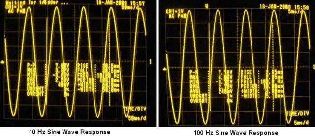
Sine wave 10 Hz and 100 Hz

Sine wave 1 kHz and 10 kHz
100 kHz and 1 MHz signals

Square wave 10 Hz and 100 Hz

Square wave 1 kHz and 10 kHz

60 W total power, 1 kHz symmetry cutoff


Thus, it becomes clear that a simple and high-quality design of an UMZCH is not necessarily made using integrated circuits - only 8 transistors allow you to achieve decent sound with a circuit that can be assembled in half a day.